Debugging, Coordinate Frames, and Finite State Machines
Today
- Brainstorming Robot Debugging Strategies
- Coordinate Frames and Coordinate Transforms in Robotics
- Finite State Machines and Studio Time
For Next Time
- Work on the the RoboBehaviors Project.
- The final project deliverables will be due Tuesday 23rd at 7PM!
- A rubric for the project is available on Canvas.
- We will have a shareout for the project on Monday Sept. 22nd in class (with a short deliverable).
- Work on the Broader Impacts assignment Part 1, due on September 30th at 7PM.
- We will have a class discussion on Thursday Oct. 2nd.
Brainstorming Robot Debugging Strategies
Debugging is the act of incrementally testing code for accurate behavior and tracing errors back through the system to resolve them. You may have encountered some debugging strategies in SoftDes. Some generic strategies for debugging software carry over to robotics programming, while novel methods may need to be included given the interaction software has with hardware.
Group Discussion
Take 10 minutes to come up with some debugging strategies for writing robotics code with the folks around you, then we’ll share out to the class. As a motivating example, let’s consider the part of the RoboBehaviors where you have to create a wall follower.
Here are some areas to consider in the debugging / development lifecycle:
- How do you ensure your code is correct (implements the strategy you expected)?
- How do you test your approach to see if it performs the task effectively (e.g., follows a person)?
- How might you tune the parameters of your approach to make it perform as best possible?
Coordinate Frames and Coordinate Transforms in Robotics
Likely you’ve encountered the notion of multiple coordinate systems before at some point in your academic career. Depending on your path through Olin, you may already be familiar with the mechanics of how to map vectors between different coordinate systems (either in 2D or 3D). In this exercise, you’ll get a chance to refresh some of this knowledge and to also gain a conceptual understanding of how the notion of multiple coordinate systems plays out in robotics.
tf2 and You
We’ve encountered a funny logistical matter when using Rviz2 to visualize our /my_point topic – we needed to change our “Fixed Frame” from /map to /odom. What’s going on? These are two different coordinate frames ROS2 uses to track a robot in a world. There are actually loads of coordinate frames we might want to be thinking about in robotics. (And you can read more about how ROS has thought about coordinate transforms here).
Let’s get a sense for how we might encounter more coordinate transforms in ROS2 by walking through this tutorial. ROS2 uses a utility called tf2 in order to track the relationships between various entities in a world. When we walk through this tutorial, we’ll be seeing how to inspect all the different transforms that are going on.
Creating a world coordinate frame
Understanding the math behind what tf2 is doing for us can be super helpful – especially when we start thinking about debugging robot behavior, adding sensors to our robots, and interacting in increasingly complex environments.
Suppose your Neato is at position 3.0m, 5.0m with a heading of 30 degrees (where counter-clockwise rotation is positive) in a coordinate system called world. Draw a picture. Make sure to label the axes of the world coordinate system (don’t worry about the z-axis).In robotics, we frequently need to express the position of various entities (e.g., obstacles, goal locations, other robots, walls, doorways, etc.). While we could express all of these positions in terms of the coordinate system world, in many situations this will be cumbersome.
Exercise: Taking the Neato as an example, make a list of the coordinate systems that you feel would be convenient to define. For each coordinate system, define its origin and give a few examples of entities that would be natural to express in that coordinate system.
base_link
Next, we’ll define base_link, which will serve as our robot-centric coordinate system. The origin of this coordinate system will be at the midpoint of the line connecting the robot’s wheels. The x-axis will point forwards, the y-axis will point to the left, and the z-axis will point up. Update your drawing to indicate the position of the base_link coordinate axes (again, don’t worry about the z-axis).
Now that we have defined our new coordinate system, we’d like to be able to take points expressed in this coordinate system and map them to the world coordinate system (and vice-versa). In order to do this, we need to specify the relationship between these two coordinate systems. A natural way to specify the relationship between two coordinate systems is to specify the position of the origin of one coordinate system in the other as well as the directions of the coordinate axes of one frame in the other. Going back to our original example we can say that the coordinate axes of the Neato’s base_link coordinate system are at position 3.0m, 5.0m with a rotation of 30 degrees relative to the coordinate axes of the world coordinate frame. We usually think of this information as defining the transformation from world to base_link. It turns out that with just this information, we can map vectors between these two coordinate systems.
From base_link to world
Exercise: Determine the coordinates of a point located at (1.0m, 0.0m) in the base_link coordinate system in the world coordinate system. First draw the point on the board to make sure everyone agrees what its location is. Once you’ve determined your answer, how can you tell if you are right?
Exercise: Determine the coordinates of a point located at (0.0m, 1.0m) in the base_link coordinate system in the world coordinate system. First draw the point on the board to make sure everyone agrees what its location is. Once you’ve determined your answer, how can you tell if you are right?
Exercise: Determine the coordinates of a point located at (x, y) in the base_link coordinate system in the world coordinate system. If you are having trouble operationalizing your answer in terms of equations, you can define it in terms of high-level operations (e.g., translations, rotations, etc.).
From world to base_link
There are multiple ways to tackle this one. We think it’s easiest to do algebraically (with your good-old i-hat and j-hat notation), but you can do it in terms of geometry / trigonometry too. Don’t get too hung up on the mechanics, try to understand conceptually how you would solve the problem.
Exercise: Determine the coordinates of a point located at (0.0m, 1.0m) in the world coordinate system in the base_link coordinate system. First draw the point on the board to make sure everyone agrees what its location is. Once you’ve determined your answer, how can you tell if you are right?
Exercise: Determine the coordinates of a point located at (1.0m, 0.0m) in the world coordinate system in the base_link coordinate system. First draw the point on the board to make sure everyone agrees what its location is. Once you’ve determined your answer, how can you tell if you are right?
Exercise: Determine the coordinates of a point located at (x, y) in the world coordinate system in the base_link coordinate system. If you are having trouble operationalizing your answer in terms of equations, you can define it in terms of high-level operations (e.g., translations, rotations, etc.).
Possible Notation
Sometimes, it can be helpful to lead with notation. Other times, it can obfuscate and confuse. Here is some notation that you could use to reason about and define coordinate systems. If this is useful to you, please go for it!
\[\begin{eqnarray} \mathbf{p}_{/W} &\triangleq& \mbox{a point, p, expressed in coordinate system W} \\ \mathbf{p}_{/N} &\triangleq& \mbox{a point, p, expressed in coordinate system N} \\ \hat{\mathbf{i}}_{N} &\triangleq& \mbox{a unit vector in the i-hat direction of coordinate system N} \\ \hat{\mathbf{j}}_{N} &\triangleq& \mbox{a unit vector in the j-hat direction of coordinate system N} \\ \hat{\mathbf{r}}_{W\rightarrow N} &\triangleq& \mbox{a vector pointing from the origin of W to the origin of N} \\ \mathbf{r}_{W \rightarrow N / N} &\triangleq& \hat{\mathbf{r}}_{W\rightarrow N}\mbox{ expressed in coordinate system N} \\ \hat{\mathbf{i}}_{N/W} &\triangleq& \hat{\mathbf{i}}_{N}\mbox{ expressed in coordinate system W} \\ \hat{\mathbf{j}}_{N/W} &\triangleq& \hat{\mathbf{j}}_{N}\mbox{ expressed in coordinate system W}\end{eqnarray}\]Static Versus Dynamic Coordinate Transformations
The relationship between some coordinate systems are dynamic (meaning they change over time) and some are static (meaning they are constant over time).
Exercise: Assume that our Neato robot can move about in the world by using its wheels. Is the relationship between world and base_link static or dynamic? Given the coordinate systems you came up with earlier, list some examples of coordinate system relationships that are static and some that are dynamic.
Finite State Machines
We have been working on developing singular robot behaviors over the last few classes. But what if we want to chain behaviors together into more complex interactions with an environment?
While there are many possible frameworks to utilize, finite state machines represent a fundamental way to switch between different actions depending on environmental (or internal) measurements.
Consider the following example from the project assignment:
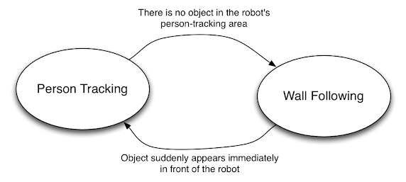
Here, the circles represent “states” that our robot can be in; in this case, a behavior that it can be executing. The arrows represent “transitions” between states, with the “transition criteria” labelling the arrow.
Finite state machines, by their name, imply the following:
- There are a finite, countable number of states that a robot can be in
- Each state is deterministic (that is, we know with certainty what state we are in)
- Given the current state of the robot, a transition to another state is deterministic based on a unique transition criteria
Here, while there are two states and two transition criteria, and there is a cycle, you can have finite state machines such that there are multiple transition criteria that can lead to different states, you can have “terminal states” where once the robot arrives in that state it stays in that state forever, and you can have internal cycles within a larger network. While they may be finite and deterministic, finite state machines can capture incredibly complex behavior – their limitation is realistically your own imagination (since everything must be explicitly defined).
Exercise 1 With your project partner, consider what behaviors you would like to include in a finite state machine, and brainstorm a list of transition criteria between these states.
Exercise 2 With your project partner, consider your implementation architecture in ROS. There are two general frameworks you could decide between (Note: there are more! But this is a common dichotomy to consider):
- Many nodes, one manager: You are running behaviors in N separate nodes, and you have one “manager node” running your FSM to coordinate between which nodes are “active” over the ROS network.
- One node, many callbacks: You run a single FSM node with the behaviors directly embedded as functionality in the FSM, accessed by a system of internal callbacks for managing what functions are accessed based on internal record keeping of states and transitions.
You can decide on any architecture, just before to clearly describe your choices in your project write-up!